Monoblock Stoppers
Monoblock Stoppers
Technical characteristics
JSC “BRP” manufactures monoblock stoppers both by own processing technique and processing technique analogous to that of leading world manufacturers.
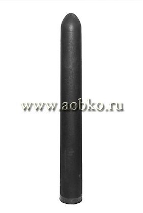
Depending on the service conditions, the stoppers may differ in geometry, material of head end (corundum-graphite or periclase-carbonaceous), fastener (metal nut, ceramic insert, thread inside the stopper body, splint).
Most of primary metals establishments when applying continuous steel casting technique, use argon blowing through tubular monoblock stoppers in order to suppress secondary tarnishing.
Supply of inactive gas through the stopper rod prevents clogging of submersible nozzle, formation of deposits of non-metallic alumina inclusions at the head end of the stopper and nonswirl nozzles, especially when teeming aluminum-killed steel. Besides, argon blowing provides formation of finer and more compact macrostructure of ingots and rolled products, decreases content of impurities in the metal, prevents drawing-in slag from the intermediate ladle, prevents vacuum formation in the pouring elements.
Argon blowing is effective in the cases when the monoblock stopper is fitted with porous insert providing argon passage while teeming. Refractory porous insert allows injecting argon in the form of small bubbles, which, due to surface-tension effect, are attached to the nonmetallic inclusions and carry them to the surface of intermediate ladle
JSC “BRP” has developed material and design of porous insert, which is installed in the monoblock stopper channel, for passing inactive gas through the stopper.
The selection of specific size of filler grains for channel porosity of the product and application of binding agent not suffering volumetric changes when in service, has allowed argon blowing during the whole teeming process run.
Application of refractory porous insert decreases inactive gas feed rate and regulates gas pressure in the stopper cavity space, bringing this pressure to the level of the pressure in the feed main. Obvious advantage of porous insert application is in the fact that it prevents metal flowing inside the stopper, thus prevents it from damage.
| Rate for grade | ||||
|---|---|---|---|---|
| SКGU | SКGPU | |||
| cylindrical body | head | cylindrical body | head | |
| Spec. 14-194-274-06 rev.1-3 | ||||
|
Mass fraction of dry substance, %: Al2O3, minimum MgO, minimum С, minimum |
- 27 |
- 13 |
- 27 |
2,5 70 13 |
| Apparent density, g/cm³, minimum | 2,50 | 2,60 | 2,50 | 2,60 |
| Open porosity, %, maximum | 17 | 20 | 17 | 20 |
| Rate for grade | |||||
|---|---|---|---|---|---|
| КУСМ | КУСМП | КУСМУ | |||
| сylindrical body | head | сylindrical body | head | ||
| GOST R 52801-2007 | |||||
|
Mass fraction, %: Al2O3 on baked substance, minimum С, minimum |
|
|
|
|
|
| Compressive strength, N/mm², minimum | - | 40 | 50 | 20 | 50 |
| Open porosity, %, maximum | 20 | 15 | 13 | 20 | 13 |
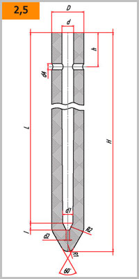
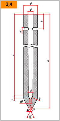
Form and dimensions GOST R 52801-2007
| Number | Dimensions of monoblock stoppers, mm | |||||||||||
|---|---|---|---|---|---|---|---|---|---|---|---|---|
| H | h1 | D | d | d1 | d2 | d3 | d4 | L | l | R1 | R2 | |
| 2 | 1050 | 100 | 95 | 35 | 30 | 10 | - | 18 | 970 | 20 | 20 | 40 |
| 3 | 1050 | 100 | 95 | 35 | 30 | 10 | 5 | 18 | 970 | 20 | 20 | 40 |
| 4 | 1150 | 100 | 130 | 42 | 38 | 10 | 5 | 18 | 1065 | 25 | 40 | 40 |
| 5 | 1150 | 100 | 130 | 42 | 38 | 10 | - | 18 | 1065 | 25 | 40 | 40 |


| Dimensions of brick, mm | Limit deviations | |
|---|---|---|
| mm | % | |
| Diameter: | ||
| up to 50 inc. | ±2 | - |
| over 50 | -4, +6 | - |
| Height |
- | ±3 |


